No communication with cluster, won't start

Relays are easy to check. They should have a circuit printed on them. Test with a 12v source and a meter.

RAB
 
Is this in the trunk near the battery? The small black plastic box near positive?
I'll check tomorrow ;)

I've got a solid 12.5V on VCDS (GCU/Mesuring block/02) so I didn't worry about that.

I see Instrument cluster are cheap nowadays, except they are all 1.4TDI
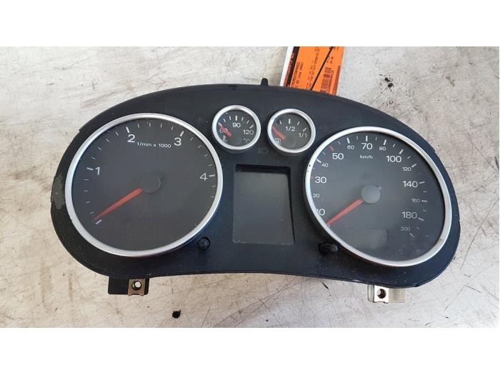
:mad:

Here's one for a 1.2tdi in case you'll need one, although for sale in Holland......


I know there can be shipping problems due to decisions made by government's, but maybe worth a try if they're willing to ship the cluster.
 
Last edited:
Yes the black box to the left of the positive terminal. Take it apart and clean all connections and reassemble.

It was clean & tight.
I shine every bits with Steel wool, did not make a change.

The 3 yellow symbols on the left side of Instrument cluster did not want to lights up today.

On https://wiki.a2-freun.de/wiki/index.php/Kombiinstrument we see a A2 Instrument cluster switched on out of the car (on a table).
And obviously the 3 red screens goes on. If mine do the same, i'll be more confident it's not broke.

How to do that, what pin for 12+ & 12- ?
(I have an old lupo3L wiring loom so I can try that clean)

Here's one for a 1.2tdi in case you'll need one, although for sale in Holland......
Thank you so much Memmo, noted.:)

 
Have you tried running an independent earth lead from a known good earth to an earth point on the instruments? Have you checked for burnt contacts in the fuses and relays? Do you have someone near by that you can temporarily swap your instrument panel with to check if their panel works in your car?
 
no, yes -all, no
Looks like my problem has no precedent.

I'm done with cleaning contacts, I'll unsheathe the Fluke.
 
On PDF (SM_24) that I give links previous page, I found

Assignment of contacts at multi-pin connectors at dash panel insert
32-pin blue connector (basic function)
1 - Terminal 15
2 - Brake lining wear
3 - Speedometer output 1
4 - Vacant
5 - Fuel gauge sender
6 - Fuel gauge warning OBD 2
7 - Terminal 31 (sender earth)
8 - Coolant temperature
9 - Terminal 31 (load earth)
10 - Oil pressure 2 (high)
11 - Engine speed signal
12 - Air conditioner shut-off
13 - Electronic throttle / glow period warning lamp
14 - Self-levelling suspension
15 - Terminal 58d
16 - Trailer turn signal
17 - Main beams
18 - Left turn signal
19 - Vacant
20 - Terminal 58s
21 - Driver's door contact
22 - Coolant level low
23 - Terminal 30
24 - Terminal 31 (load earth)
25 - Fuel consumption signal
26 - Right parking light
27 - Left parking light
28 - Speedometer input
29 - Brake pad / brake fluid
30 - S contact
31 - Speedometer output 2
32 - ESP/TCS


32-pin green connector (supplementary function)
1 - Door contact (all doors)
2 - Transponder 1
3 - Vacant
4 - Vacant
5 - W wire
6 - Tailgate
7 - Right turn signal
8 - Vacant
9 - Vacant
10 - airbag
11 - Standing time output
12 - Terminal 61
13 - Parking brake / BRAKE
14 - Check / fault in engine electrical system
15 - Oil level / oil temperature
16 - Vacant
17 - Transponder 2
18 - CAN high speed (drive “+”)
19 - CAN high speed (drive “+”)
20 - CAN high speed (drive “screen”)
21 - ABS
22 - CAN low speed (convenience “+”)
23 - CAN low speed (convenience “-”)
24 - CAN low speed (convenience “screen”)
25 - Bonnet switch
26 - Tank flap switch
27 - Belt buckle
28 - K wire
29 - Ambient temperature input
30 - Terminal 58de (ext. dimmer potentiometer)
31 - Selector lever display
32 - Vacant


32-pin grey connector (multi-function display ; Highline-dash panel insert only)
1 - Menu switch (menu)
2 - Menu switch (out A)
3 - Menu switch (out B)
4 - Menu switch (enter)
5 - CAN high speed (display “+”)
6 - CAN high speed (display “-”)
7 - CAN high speed (display “screen”)
8 - Passenger's door contact
9 - Door contact, rear right
10 - Door contact, rear left
11 - Enable
12 - Clock
13 - Data
14 - Brake lights
15 - Washing water level
16 - Tail lights / dipped beams
17 - On-board computer, left
18 - On-board computer, right
19 - On-board computer, reset
20 - Vacant
21 - Vacant
22 - Vacant
23 - Key branch 1 Navigation system
24 - Key branch 2 Navigation system
25 - Key branch Telematics
26 to 32 - Vacant

If i take the instrument cluster home, what are the "+", the "Terminal 15"?
"-" are "Terminal 31"?
 
This page contains details of the terminal references.
Thank you very much!
So Terminal 15 battery+ through ignition switch & Terminal 30 from battery+ direct

If the cluster is not broke, the T32(blue connector)/pin1(Terminal 15) look like the perfect guilty one
The pin23(Terminal 30) must be OK because some symbols illuminate, but nothings else.

This T32/1 goes to "B163 Positive (+) connection -1- (15), in interior wiring harness", something to worry?
but also to "J532 Voltage stabiliser", can this be broke?

It look like J532 is under left seat ; so that might be connected to my cracked drain hole finally...
 
Interesting quote "It look like J532 is under left seat ; so that might be connected to my cracked drain hole finally..."A voltage stabiliser with a broken drain hole. I assume you have under floor damage. There is no damage to the voltage regulator(s) and still securely mounted or damaged wiring?
 
Last edited:
I have not under floor damage, my drain plug was cracked so it isn't doing it's job.

EDIT : I have no marks of dirt or water neither,
so I stop here because it's not the subject
 
Last edited:
With a needle inserted in various place in 32-pin blue connector, I have 12V on pin1(Terminal 15) & pin23(Terminal 30)
Then 0 Ω with earth on pin9 & pin24 (Terminal 31 load earth)
BUT a positive Ω value on pin7 - Terminal 31 (sender earth)

This Terminal 31 (sender earth) is known as (269)Earth connection (sender earth) -1-, in dash panel wiring harness on Current Flow Diagram (460 page PDF available here ; no need of ELSAWIN in this case).

This might be my problem, no?
Is this here? (picture of Gary JIGSAW -thanks!- who say mine was slightly corroded as it goes and imagine its the condensation from the quarter light glass running down may of caused this.

What can I do to NOT remove the dash?

index.php

,
 
This Terminal 31 (sender earth) or (269)Earth connection (sender earth) -1-, in dash panel wiring harness appears at 4 different points :
All of them are brown & white cables, but not same section
- T32/pin7 Instrument Cluster's blue connector (0.22mm)
- pin2 of headlight range connector (0.35mm)
- T17/pin11, brown connector in front left footwell, for Coolant temperature sender (0.5mm)
- T10f/pin8, blue connector left A pillar, for Coolant shortage indicator switch (0.5mm)

I unplug these 4 connectors and I have about the same 1M Ω value (but very unstable value, what does this usually mean ?) with earth on each (so they are all 4 interconnected, 0 Ω between them)
Can I use T Tap Electrical Connectors on the 2 main 0.5mm cables to make 2 new earth connection and call it a day?

EDIT: Earth connection solved but no progress, I'll test the Instrument Cluster on a bench...
May this bad earth damaged the Instrument Cluster?
 
Last edited:
So I connected the Instrument Cluster at home to a 14.1V power supply (12V battery and its charger) to see how it behave.

The "-" to these 3 pin:
7 - Terminal 31 (sender earth)
9 - Terminal 31 (load earth)
24 - Terminal 31 (load earth)

The "+" to pin:
23 - Terminal 30 (as battery+ direct)
The green symbol about lights illuminate

Then I manually connect the "+" to pin:
1 - Terminal 15 (as battery+ through ignition switch)
Most of the symbols illuminate, but none of the 3 red screen

Should I have connected something else?
Should I perform an other test? What?
What should I understand from this one?
 
Last edited:
One question until I found out about the Instrument Cluster,
can we completely disactivate the immotronic?

As I understand the problem on my car, the ECU, GCU & ABS are fine, the engine starts, must be drivable
but engine stop due to the lack of answer from Instrument Cluster/ immotronic.

The risk of the car being stolen is low, or way lower than getting another electronic issue,
I am then not interested in keeping this immotronic feature (this A2 or my LUPO 3L).

This problem happen at home, good, but if that happened far far away, as I sometime cross all Europe, this car might be in ashes already...
I would avoid ;)
 
I would say that your instrument cluster is faulty
On the A2 it is much more than just instruments, it is also the CAN gateway which means most signals flow into and out of the instrument cluster
It is an integral part of the engine immobiliser

The key fob and the instrument cluster and the engine ecu are the three components of the immobiliser system
If any one of them fails the immobiliser will not turn off resulting in engine running for around 1second only

It is possible to turn off the immobiliser in the engine ecu if you have the correct cable/ software/ know how
It would not be correct for me to describe this any further on a public forum as it would effectively tell the owl world how to disable the immobiliser on a VAG car

Paul


Sent from my iPhone using Tapatalk
 
It would not be correct for me to describe this any further on a public forum as it would effectively tell the owl world how to disable the immobiliser on a VAG car
Thank you for your feedback.
I'm completely with you about not describing any further how to remove the Immotronic.

The car will go to a programmer specialist once I get the instrument Cluster replacement.
I don't feel able to do all the adaptation (changing total kilometers etc), so he'll do this Immotronic deletion too.

Maybe he will be nice enough to tell me how, so I can duplicate the process on my LUPO 3L...
The remaining value of my cars are low enough now. In the good old time, bad instruments never prevent a car to run, I want this to stay that way. Good luck with the TFT ones after 20 years!!

One last question, what is the differences between "sender earth" & "load earth" ?
Am I right to connect Terminal 31 (sender earth) directly to the body metal to avoid positive Ω value to earth?
 
Last edited:
I am not an electrician so may well BE WRONG when I say this. I think sender earth is when an earth signal is sent to a component to switch it rather than sending positive. PLEASE CHECK AND UNTIL YOU KNOW DO NOT EARTH THE SENDER EARTH TO THE BODY.
 
Back
Top