This may assist you. Please check it is the same as your car as a few issues are appearing in the manuals not reflecting UK spec cars.
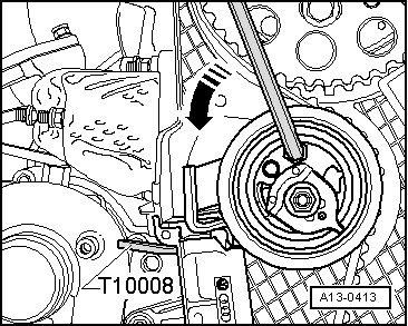
Insert a hexagon key into the hexagon socket as far as the stop and use it to push the tensioning roller anti-clockwise -arrow- until you can lock the toothed belt tensioner with locking plate -T10008-.
Note
t Insert the hexagon key as far as stop, to prevent damage.
t The toothed belt tensioner is oil-damped and can therefore only be compressed slowly by applying constant pressure.
– Loosen securing nut for tensioning roller.
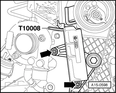
– Unscrew bolts -arrows- and detach toothed belt tensioner.
– Remove toothed belt.
Installing (adjusting valve timing)
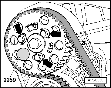
l Camshaft locked with locking pin -3359-.
l Crankshaft locked in position with crankshaft stop -T10050-.
l Tensioning roller locked with locking plate -T10008-.
Note
t Toothed belt adjustment must always be performed when the engine is cold.
t The crankshaft must not be at “TDC” at any cylinder when the camshaft is turned. Otherwise, there is a risk of damage to valves and piston crowns.
– Screw in bolts -arrows-, but do not tighten.
l The camshaft sprocket must just about still turn, and must not tilt.
– Turn the camshaft sprocket in its elongated hole clockwise until the stop.
– Fit toothed belt first onto camshaft sprocket, tensioning roller, crankshaft sprocket and then onto coolant pump sprocket.
– Install toothed belt tensioner.
Adjust toothed belt tension as follows:
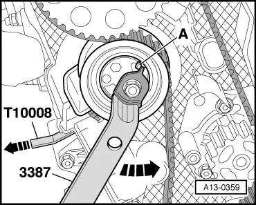
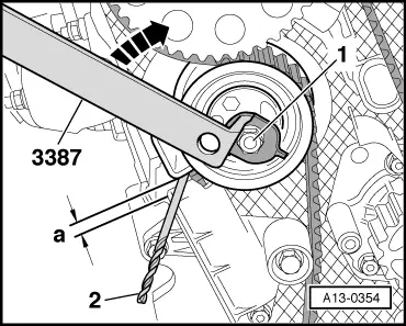
– Turn eccentric adjuster anti-clockwise -arrow- onto stop -A- using 2-hole pin wrench -3387-.
– Remove locking plate -T10008-.
– Wrap insulating tape around tip and shaft of 4.0 mm Ø drill bit to avoid cuts.
– Gradually relieve pressure on the tensioner and allow it to turn clockwise -arrow- until you can pull the shaft of a Ø 4.0 mm drill bit -item 2- through between the tensioning lever and the housing of the tensioner.
l Dimension -a- = 4.0 ± 1.0 mm.
Note
t Leave sufficient tolerance when adjusting, dimension -a- is reduced when tightening tensioning roller nut.
t Dimension -a- is reduced when the engine is at operating temperature.
– Hold tensioning roller in this position and tighten securing nut to 20 Nm + 45° (1/8 turn).
– First tighten bolts -arrows- for camshaft sprocket to 25 Nm.
– Remove locking pin -3359- and crankshaft stop -T10050-.
Caution
The engine must only be turned at the crankshaft, in the direction of normal engine rotation (clockwise).
– Turn crankshaft two rotations in normal direction of rotation until it is again positioned just before “TDC”.
– Check again that dimension -a- is obtained between tensioning lever and housing of tensioner.
l Dimension -a- = 4.0 ± 1.0 mm.
If dimension -a- is not obtained, re-tension the tensioning roller as follows:
– Hold tensioning roller with 2-hole pin wrench -3387- , slacken nut -1- and relieve pressure on tensioner -arrow- until dimension -a- is obtained.
l Dimension -a- = 4.0 ± 1.0 mm.
– Hold tensioning roller in this position and tighten securing nut to 20 Nm + 45° (1/8 turn).