KekseKaempfer
A2OC Donor
Modify your indicator/flasher module so that you can use LED indicator bulbs.
Inspired by this article. http://www.audizine.com/forum/showthread.php/532676-Diy-Led-turn-indicator-(hazard-switch)-mod-tutorial
What you will need:
1 0R33 resistor (0.33 ohm) 5W: http://www.ebay.co.uk/itm/201396809095
2x 220R resistor 1/4W
A soldering iron, solder and probably a solder sucker or small wire cutters.
A small flat bladed screwdriver.
Heatshrink tubing or sheathing.
A quick note about the value of the 0R33 resistor. As far as I can work out, 0R33 is a value that seems to work in a generic case. I personally have LED, front and rear and a filament repeater. If you choose to do this mod, I believe 0R33 will be a good choice although smaller values also seem to work for me down do 0R15. That said, if you are interested in just replacing say the front or rear bulbs, then you will need to use a smaller resistor. Using the 0R33 resistor in the case of a single LED seems to cause problems with relay oscillation on activation of the indicator switch. I think this is down to the additional 220R resistors. So for the case of one LED bulb, you will need to find out the nominal current draw for your LED bulb and calculate your ideal resistor value based on this formula.
V/A = R.
In order to get the relay to NOT hyperflash with a LED bulb V in this formula needs to be 0.47V
So assuming you have 1 filament bulb (21w) I side repeater (5W) and an LED bulb, 100mA
your total current draw will be 1.75A + 0.42A + 0.1A = roughly 2.25A. Assuming you remove your LED you want hyperflash to start so reduce the current by half of the LED current (50mA) leaves 2.2A roughly.
Edited 18/09/2021
So the resistor you need is 0.049V / 2.2 = 0R022 not much different from stock. As you can see from the figures it is really difficult to use this hyperflash function with a combination of LEDs and filament bulbs because the filament bulbs take SO much more current. If you have the time and patience, you can tune the resistor size, but quite honestly, going for a larger resistor and losing the hyperflash is easiest. In any event, LED bulbs *should* last a lot longer and be more reliable that regular bulbs. If you are modding for a single bulb you shouldn't need to add the 220R resistors, there should still be enough current in the system to activate the relay correctly. See note in step 9.
Here is a link to the flasher IC documentation which gives all the relevant information on the flasher IC in the relay
http://www.mouser.com/ds/2/36/doc4726-29542.pdf
flickr album:

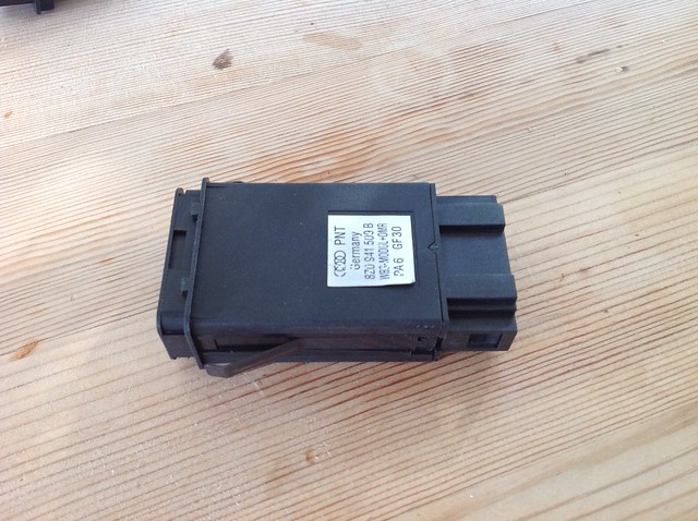
1. Remove your relay from the car
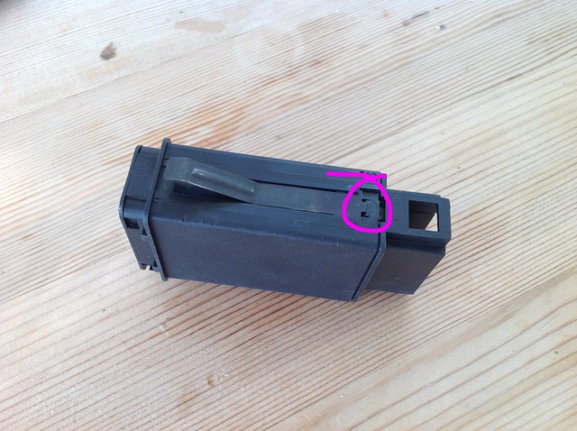
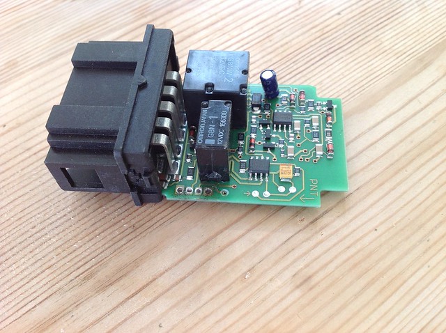
2. Open up the relay by sliding the screwdriver in to release the clips on either side holding the outer case of the relay to the connector end. Once free, the cover should just slide off and you will be left with the naked board. You don't need to remove the metal clips.
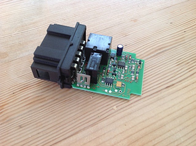
3. Take a moment to look at the relay. The shunt resistor is the shiny silvery thing that will be the focus of this mod. It needs to come out. It has 4 pins in 2 pairs, just to complicate things.
4. Remove the existing shunt. To do this you can either just cut it off, Or if you ever want to return the relay to stock , you can unsolder it using your solder sucker and some patience.
5. I chose to unsolder for this how to. It allows me to insert the new resistor through the holes and solder across the 2 pads on the underside of the board.
Note pics are post me soldering the additional resistors (step 9)
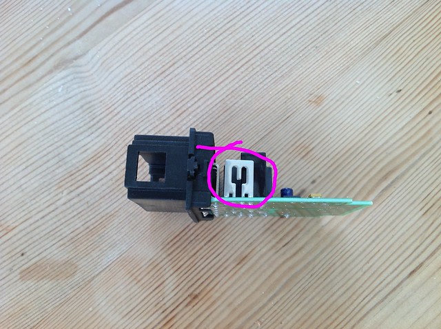
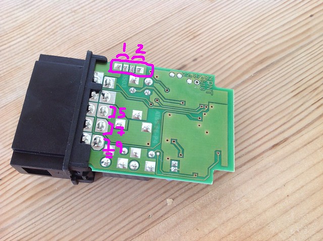
This pic shows the relevant pins. The shunt pads in the square with each of the pairs shown. These pairs of pads need to remain connected.
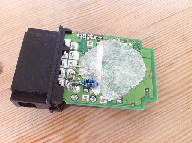
6. Get your 0R33 resistor and poke it through the holes and solder it on where the old shunt used to be. Make sure you solder the wire of each end of the new resistor to the 2 pads that were connected to each half of the old shunt. In the pic you can see that I have bent the pins of the new resistors over and have soldered across the pairs of pads. My relay also had to have a cut track reconnected after a previous modification experiment.
7. Make sure that when you solder in your new resistor that it is away from the relay. There won't be much heat but the new resistor is a fat old thing and you want to be able to get the cover back on. Mine is a little too close and rubs on the casing when put back on.
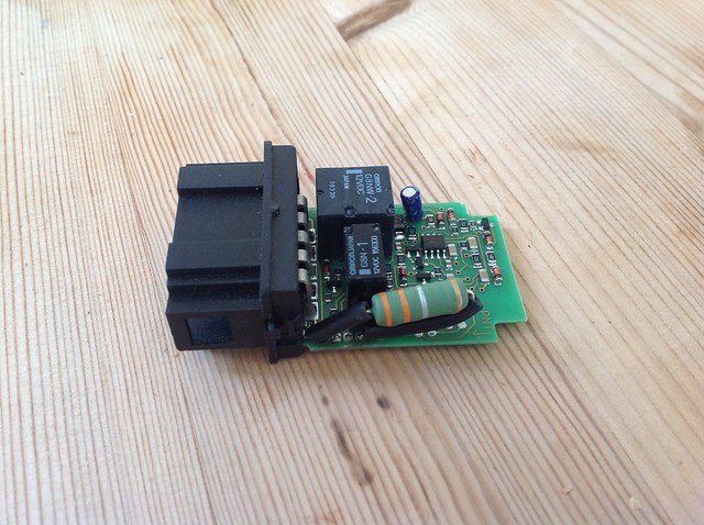
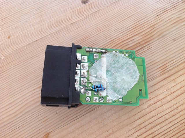
8. If you have chopped the old shunt off, just tin and solder the resistor to the remains of the old shunt. In this pic i had done just that. Just soldered the resistor to the remnants of the shunt on top of the board. Here the resistor is free of the relay and doesn't rub.

9. The use of very low current LED bulbs *may* have an effect on the IC that controls the flashing. There is a pin on the IC that controls the status of the flashing and this pin needs to draw a certain amount of current. In order to make sure that enough current is drawn from this pin we are going to add a couple of 220R resistors to earth and the switch pins of the relay, Pins 9, 7 and 5. These can be seen soldered in place but may not be necessary. It all depends on the bulbs you are using. So you could test your modified relay with just the shunt replacement before soldering these additional resistors in place. I assume you would be using some heatshrink on bare wires, unlike my attempt. One thing to note though is that there is very little room between board and casing for these 220R resistors And it is almost impossible to solder them on the top. Caution need to be taken when reassembling.
Edit. I can confirm that having LED bulbs all round, including repeaters, you WILL need to add these resistors.
10. Test the relay, and once working. Pop the cover back on and reassemble your car.
Inspired by this article. http://www.audizine.com/forum/showthread.php/532676-Diy-Led-turn-indicator-(hazard-switch)-mod-tutorial
What you will need:
1 0R33 resistor (0.33 ohm) 5W: http://www.ebay.co.uk/itm/201396809095
2x 220R resistor 1/4W
A soldering iron, solder and probably a solder sucker or small wire cutters.
A small flat bladed screwdriver.
Heatshrink tubing or sheathing.
A quick note about the value of the 0R33 resistor. As far as I can work out, 0R33 is a value that seems to work in a generic case. I personally have LED, front and rear and a filament repeater. If you choose to do this mod, I believe 0R33 will be a good choice although smaller values also seem to work for me down do 0R15. That said, if you are interested in just replacing say the front or rear bulbs, then you will need to use a smaller resistor. Using the 0R33 resistor in the case of a single LED seems to cause problems with relay oscillation on activation of the indicator switch. I think this is down to the additional 220R resistors. So for the case of one LED bulb, you will need to find out the nominal current draw for your LED bulb and calculate your ideal resistor value based on this formula.
V/A = R.
In order to get the relay to NOT hyperflash with a LED bulb V in this formula needs to be 0.47V
So assuming you have 1 filament bulb (21w) I side repeater (5W) and an LED bulb, 100mA
your total current draw will be 1.75A + 0.42A + 0.1A = roughly 2.25A. Assuming you remove your LED you want hyperflash to start so reduce the current by half of the LED current (50mA) leaves 2.2A roughly.
Edited 18/09/2021
So the resistor you need is 0.049V / 2.2 = 0R022 not much different from stock. As you can see from the figures it is really difficult to use this hyperflash function with a combination of LEDs and filament bulbs because the filament bulbs take SO much more current. If you have the time and patience, you can tune the resistor size, but quite honestly, going for a larger resistor and losing the hyperflash is easiest. In any event, LED bulbs *should* last a lot longer and be more reliable that regular bulbs. If you are modding for a single bulb you shouldn't need to add the 220R resistors, there should still be enough current in the system to activate the relay correctly. See note in step 9.
Here is a link to the flasher IC documentation which gives all the relevant information on the flasher IC in the relay
http://www.mouser.com/ds/2/36/doc4726-29542.pdf
flickr album:

1. Remove your relay from the car
2. Open up the relay by sliding the screwdriver in to release the clips on either side holding the outer case of the relay to the connector end. Once free, the cover should just slide off and you will be left with the naked board. You don't need to remove the metal clips.
3. Take a moment to look at the relay. The shunt resistor is the shiny silvery thing that will be the focus of this mod. It needs to come out. It has 4 pins in 2 pairs, just to complicate things.
4. Remove the existing shunt. To do this you can either just cut it off, Or if you ever want to return the relay to stock , you can unsolder it using your solder sucker and some patience.
5. I chose to unsolder for this how to. It allows me to insert the new resistor through the holes and solder across the 2 pads on the underside of the board.
Note pics are post me soldering the additional resistors (step 9)
This pic shows the relevant pins. The shunt pads in the square with each of the pairs shown. These pairs of pads need to remain connected.
6. Get your 0R33 resistor and poke it through the holes and solder it on where the old shunt used to be. Make sure you solder the wire of each end of the new resistor to the 2 pads that were connected to each half of the old shunt. In the pic you can see that I have bent the pins of the new resistors over and have soldered across the pairs of pads. My relay also had to have a cut track reconnected after a previous modification experiment.
7. Make sure that when you solder in your new resistor that it is away from the relay. There won't be much heat but the new resistor is a fat old thing and you want to be able to get the cover back on. Mine is a little too close and rubs on the casing when put back on.
8. If you have chopped the old shunt off, just tin and solder the resistor to the remains of the old shunt. In this pic i had done just that. Just soldered the resistor to the remnants of the shunt on top of the board. Here the resistor is free of the relay and doesn't rub.
9. The use of very low current LED bulbs *may* have an effect on the IC that controls the flashing. There is a pin on the IC that controls the status of the flashing and this pin needs to draw a certain amount of current. In order to make sure that enough current is drawn from this pin we are going to add a couple of 220R resistors to earth and the switch pins of the relay, Pins 9, 7 and 5. These can be seen soldered in place but may not be necessary. It all depends on the bulbs you are using. So you could test your modified relay with just the shunt replacement before soldering these additional resistors in place. I assume you would be using some heatshrink on bare wires, unlike my attempt. One thing to note though is that there is very little room between board and casing for these 220R resistors And it is almost impossible to solder them on the top. Caution need to be taken when reassembling.
Edit. I can confirm that having LED bulbs all round, including repeaters, you WILL need to add these resistors.
10. Test the relay, and once working. Pop the cover back on and reassemble your car.
Last edited: