wilco184
Member of the year 2015
Hi,
I've had my current A2 since December of 2014. After fitting a few nice retrofits and modifications such as the twin interior boot light, dual tone horn and more recently RNS-E, I've found it really enjoyable to be undertaking work like this and improving my car in the process. Like a few other members of the A2OC, I enjoy installing factory options that my car doesn't have. There's a certain pleasure to be had from making up wiring looms, changing parts and then being pleased with the results. It's good fun.")
A few months after swapping to a double DIN dashboard and installing RNS-E, a new question arose. What should I do next? I had narrowed down my choices to two possible outcomes. Bose or rear electric windows. Shortly after, an ideal Bose kit was listed on eBay and so, I put in a offer which was accepted. Sadly, there was a 'situation' with the Bose kit and the net result is that it did not get to me. Disappointing, yes, hence my choice of retrofit changed to rear electric windows.
Which brings me neatly to the purpose of this thread, to document my rear electric windows retrofit. I'll have to document this over a couple of posts. It's pretty photograph heavy, but a picture tells a thousand words, as they say.
Armed with a copies of ETKA, ElsaWin and Tom's (Timmus) excellent post here, I started collecting the parts I would need for the installation. The list is as follows:
- Window regulators.
- Rear drivers and passenger side motors.
- A collection of pins, repair wires and connectors.
- Rear door cards for electric windows.
- The drivers door switch.
- A spare roll of loom tape.
- The correct 30A fuse.
- The necessary wires.
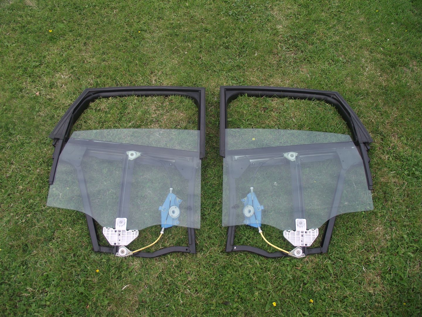
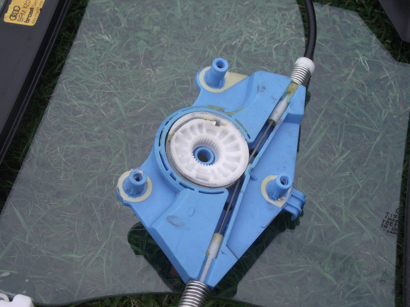
Regarding the window regulators, I had purchased the complete regulator with the window frame and glass. This would enable me to simply remove the window frame from my car, and then drop in the new ones; as opposed to disassembling each side further. Pictured below are the complete window frames. Note the different motor mounting points, with their 'splined socket'.
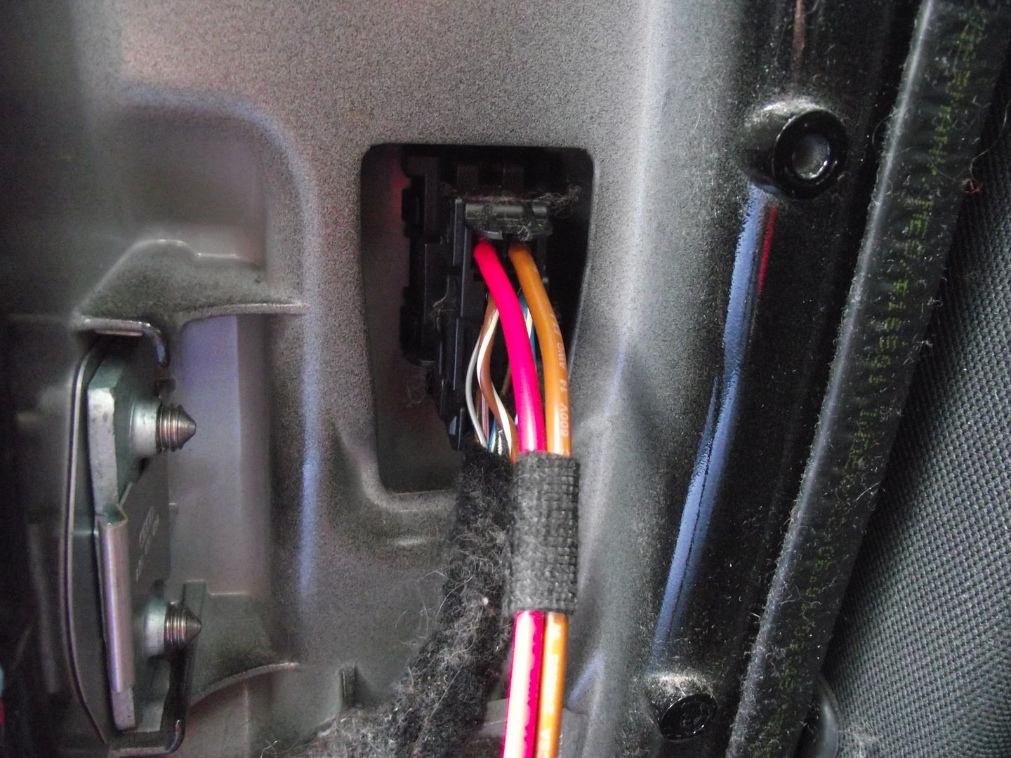
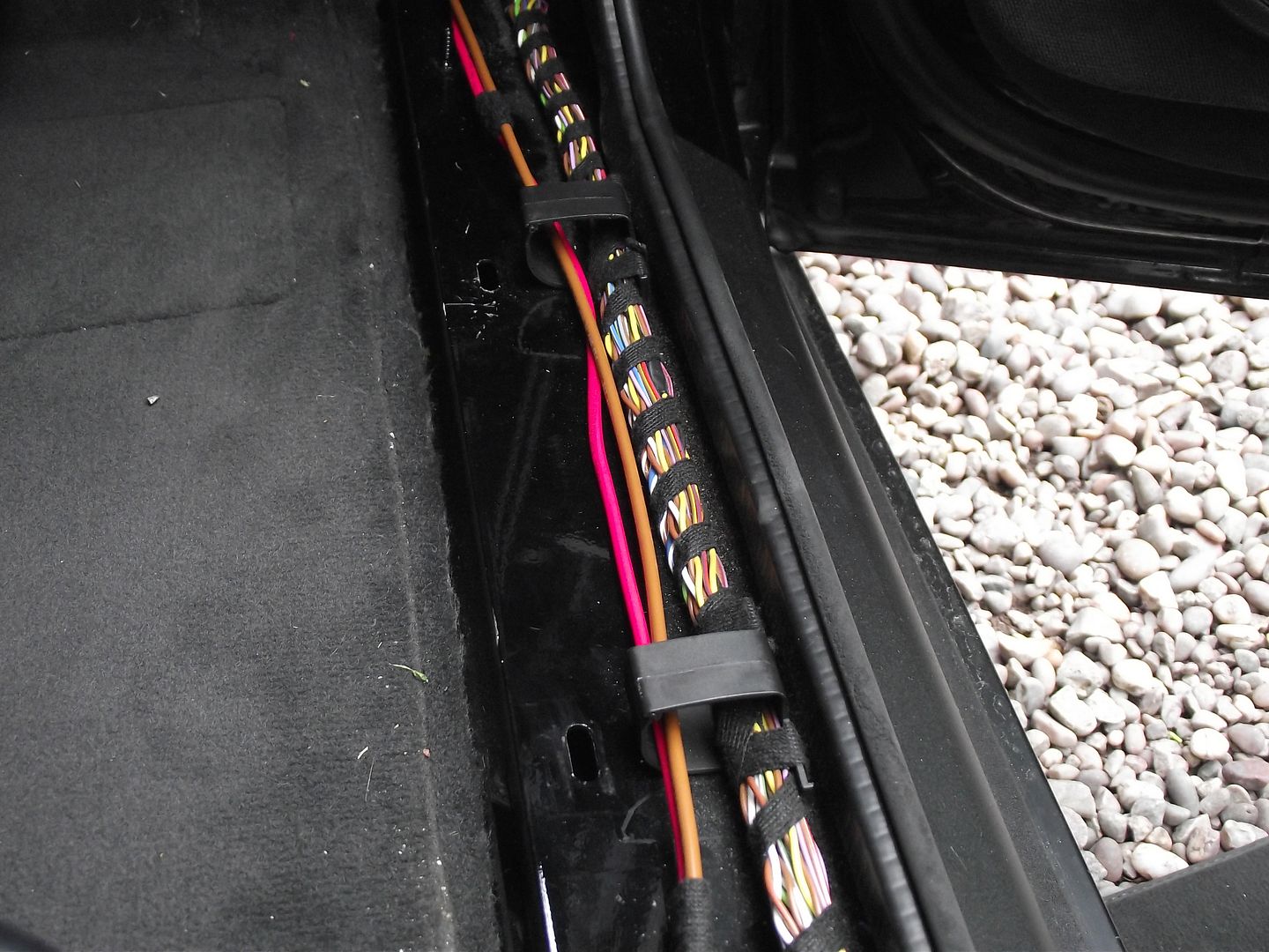
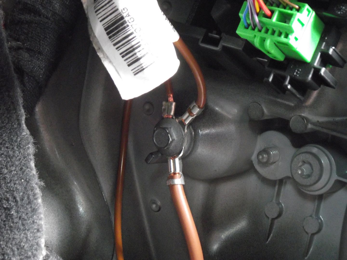
I started the retrofit by running the 2.5mm 'power' cables to each of the B pillars, on the inside of the car. These wires are permanent live feeds used to power the window motors themselves. The wires run from a main 12V connection in the space under the passenger footwell, to a 30A slow blow fuse situated at the bottom of the passenger A pillar, across the dashboard, along the sills and then to the B pillar terminal blocks. On the return path, a 2.5mm earth cable must be installed from the terminal blocks to a suitable earthing point on the car's chassis. I chose the earth connections at the bottom of the A pillars. In the pictures below, the cables have been loosely inserted ready to be wrapped properly, later on. There's something wrong in the first photo, 10 points to the person that spots it! It's been corrected now, don't worry.
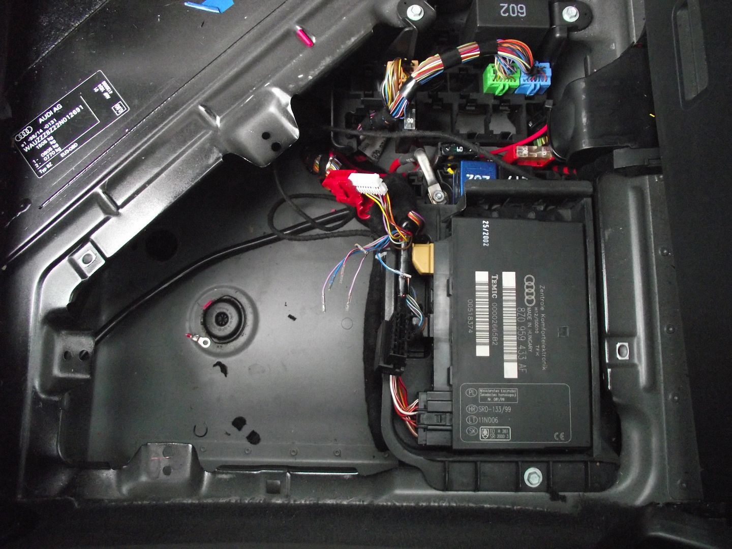
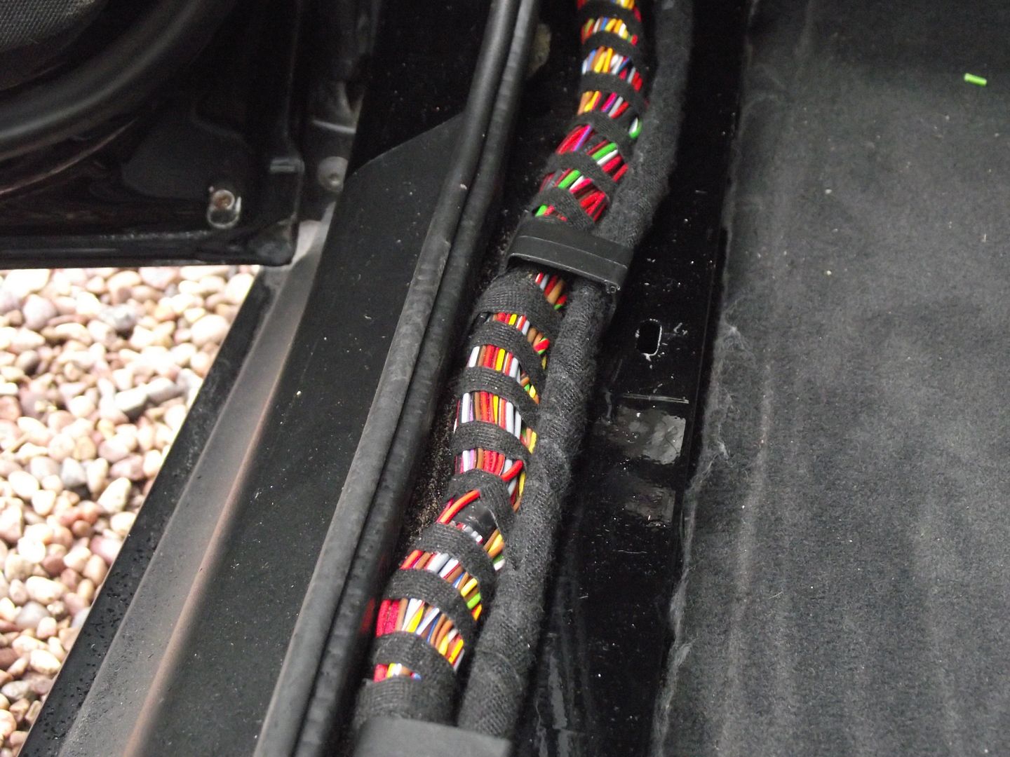
The existing wires for controlling the rear door locks must be disconnected from the CCCU, as they are no longer necessary. The reason for this being that the 7 wires needed each side for controlling the door locks are now taken from the window module inside each door. The window modules now control the door locks directly, getting instructions from the CCCU over CAN-BUS. With manual rear windows fitted at the factory, there are no CAN wires going to the rear doors as there is no requirement for them. As such, they must be fitted along with a couple more wires. The new wires are spliced into the A pillar connections for the front door, as the K line and CAN connections form a 'bus'. In total, each side's B pillar block has 9 wires going to it. CAN high and low, a K line connection, two small current 12V feeds, the two speaker connections, a 2.5mm 12V connection and a 2.5mm earth connection, as mentioned above. Personally, I don't match the correct colours of my retrofitted wiring, but the connections are the same. Some pins are no longer needed at the CCCU end - connector 2 can be cut off entirely, as well as pins 8, 12, 13, 14, 15 and 18 from connector 4. The photos below show the pins that are no longer required being removed from the CCCU connections and the new wrapped up loom running along the sill to the appropriate connections at the A pillar.
I've had my current A2 since December of 2014. After fitting a few nice retrofits and modifications such as the twin interior boot light, dual tone horn and more recently RNS-E, I've found it really enjoyable to be undertaking work like this and improving my car in the process. Like a few other members of the A2OC, I enjoy installing factory options that my car doesn't have. There's a certain pleasure to be had from making up wiring looms, changing parts and then being pleased with the results. It's good fun.
A few months after swapping to a double DIN dashboard and installing RNS-E, a new question arose. What should I do next? I had narrowed down my choices to two possible outcomes. Bose or rear electric windows. Shortly after, an ideal Bose kit was listed on eBay and so, I put in a offer which was accepted. Sadly, there was a 'situation' with the Bose kit and the net result is that it did not get to me. Disappointing, yes, hence my choice of retrofit changed to rear electric windows.
Which brings me neatly to the purpose of this thread, to document my rear electric windows retrofit. I'll have to document this over a couple of posts. It's pretty photograph heavy, but a picture tells a thousand words, as they say.
Armed with a copies of ETKA, ElsaWin and Tom's (Timmus) excellent post here, I started collecting the parts I would need for the installation. The list is as follows:
- Window regulators.
- Rear drivers and passenger side motors.
- A collection of pins, repair wires and connectors.
- Rear door cards for electric windows.
- The drivers door switch.
- A spare roll of loom tape.
- The correct 30A fuse.
- The necessary wires.
Regarding the window regulators, I had purchased the complete regulator with the window frame and glass. This would enable me to simply remove the window frame from my car, and then drop in the new ones; as opposed to disassembling each side further. Pictured below are the complete window frames. Note the different motor mounting points, with their 'splined socket'.


I started the retrofit by running the 2.5mm 'power' cables to each of the B pillars, on the inside of the car. These wires are permanent live feeds used to power the window motors themselves. The wires run from a main 12V connection in the space under the passenger footwell, to a 30A slow blow fuse situated at the bottom of the passenger A pillar, across the dashboard, along the sills and then to the B pillar terminal blocks. On the return path, a 2.5mm earth cable must be installed from the terminal blocks to a suitable earthing point on the car's chassis. I chose the earth connections at the bottom of the A pillars. In the pictures below, the cables have been loosely inserted ready to be wrapped properly, later on. There's something wrong in the first photo, 10 points to the person that spots it! It's been corrected now, don't worry.


The existing wires for controlling the rear door locks must be disconnected from the CCCU, as they are no longer necessary. The reason for this being that the 7 wires needed each side for controlling the door locks are now taken from the window module inside each door. The window modules now control the door locks directly, getting instructions from the CCCU over CAN-BUS. With manual rear windows fitted at the factory, there are no CAN wires going to the rear doors as there is no requirement for them. As such, they must be fitted along with a couple more wires. The new wires are spliced into the A pillar connections for the front door, as the K line and CAN connections form a 'bus'. In total, each side's B pillar block has 9 wires going to it. CAN high and low, a K line connection, two small current 12V feeds, the two speaker connections, a 2.5mm 12V connection and a 2.5mm earth connection, as mentioned above. Personally, I don't match the correct colours of my retrofitted wiring, but the connections are the same. Some pins are no longer needed at the CCCU end - connector 2 can be cut off entirely, as well as pins 8, 12, 13, 14, 15 and 18 from connector 4. The photos below show the pins that are no longer required being removed from the CCCU connections and the new wrapped up loom running along the sill to the appropriate connections at the A pillar.


Last edited:


