LED bulbs - would this work?

I think you might be mistaking my use of 'bulb out' there. I'm specifically talking about the input to the comparator pin7 on the flasher IC.

Chris

Hi Chris, I am DEFINITELY mistaken, "the input to the comparator pin7 on the flasher IC." is like another language to me, so I will bow out of the technical talk about this one.

Sorry

Steve B
 
Hi Chris,

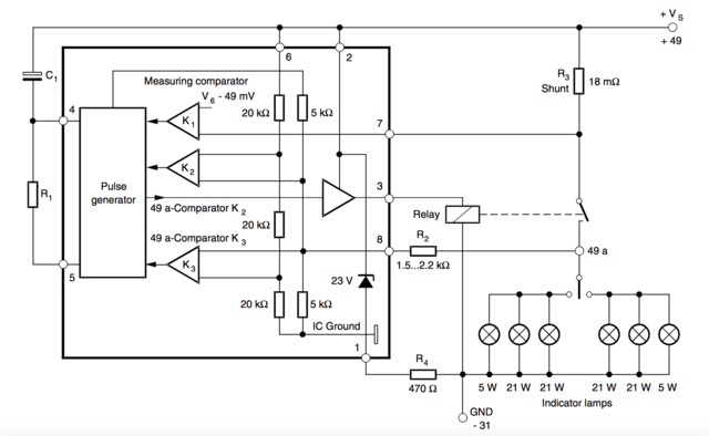
I know what you mean. If you tied pin 7 to ground, through a resistor, then you would still get the hyper flashing unfortunately. K1 (pin 7) needs a voltage of 49 mV to operate correctly. Good thinking though.

The 49 mV is dropped across the shunt resistor. So, for more drop at less current, you need a higher resistance shunt. Perhaps the 0.33 Ohm resistor that I used (0.018 Ohm OEM) is just too much and is dropping the voltage at pin 8 too low; causing it not to work. I only saw one account of 0.33 being used, with most others using 0.12 Ohms instead. I think this is the next thing to try.

Unfortunately, I'm away for a week now with work. If anyone else wants to try replacing the shunt, I'd certainly appreciate the results! :)

Regards,

Matt.


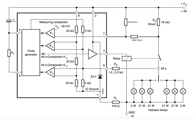
Here's what I was thinking. If you cut the link to the shunt resistor and use 2 resistors to keep the pin at something above 49mV the pin will never see the change in load.

Edit. That is pin 7 I'm referring to

The other way of course would be to accept the fact that the IC is going to flash 2x and tweak the resistor on the oscillator to slow it down again.


Chris
 
Last edited:
Here's what I was thinking. If you cut the link to the shunt resistor and use 2 resistors to keep the pin at something above 49mV the pin will never see the change in load.

Edit. That is pin 7 I'm referring to

The other way of course would be to accept the fact that the IC is going to flash 2x and tweak the resistor on the oscillator to slow it down again.


Chris

That's an excellent idea Chris. :D I must apologise, I misunderstood what you meant before, but that makes perfect sense.

There's 4 solder points on the shunt, two either side of the 18 milli Ohm load. Two are for the power to the bulbs, and then the other two are for between the Vs and pin 7 of the IC. There's no reason why we can't separate the two for pin 7 from the bulbs, and then wire in a simple voltage divider between Vs, pin 7 and ground. I'll try and draw up a diagram.

The brilliance of this is that the bulbs still receive the full supply voltage, no extra heat is created inside the flasher housing and the resistors can be smaller and cheaper. Excellent.

Fantastic work Chris.

Regards,

Matt.
 
Well, if it works ... Even if it did bypass the bulb loss circuit, it still might not be enough. Pin 8 is also concerning me. With the new LED bulbs drawing a lot less current, pin 8 might not get the voltage it needs to trigger the start flash. That may be why the guy from the article who replied added two additional resistors.

Chris
 
Hmm indeed, yes.

I couldn't understand why he used 220 Ohm resistors though; 220 Ohms at 12V doesn't give you 1 watt, so I'm not sure what that causes. Perhaps we could just try and disable the hyper flashing and then see what happens. :)

Matt.
 
So, here's the original schematic.


And here's the one with the modified shunt voltage divider. Do you think this will work?


Matt.
 
You'd need to tie to a constant ground (not through the relay switch I think. But If you think it's a sound idea , then yes. On the caveat that I've not done electronic circuit design for over 20 years.

If it does work of course you'd need to be vigilant as a blown bulb wouldn't hyper flash any more.

Chris
 
If it does work of course you'd need to be vigilant as a blown bulb wouldn't hyper flash any more.
Chris

Indeed, that is an important safety feature. I hadn't really considered that!

If one of your bulbs blow and you think you are indicating, that is not ideal, but I suppose that it is only going to potentially annoy other drivers rather than cause an accident.

But I am hoping that the LED bulbs will have a much longer life, if they are decent quality they should outlast me, if not the car!
Also, every time you lock or unlock the car the indicators flash, so you can check them pretty often as well.

Steve B

It isn't going to be too much of a problem to retain the double flash, for a bulb out I don't think. The timer IC is designed to be programmable based on the current draw of the bulbs. The problem is that every bulb you buy (LED) will likely have a slightly different effective wattage rating, or current draw. As a result, the replacement of the shunt resistor that Matt has already tried will need to be for one that has been calculated based on the bulbs you are using. In most cases a general replacement of the resistor will be OK, however it may not work for everybody. It'll depend on on the bulbs they are using. If Matt can can get something working short term without the bulb detection in the relay, that would be a good start. I'd love to be of assistance to him, but I don't have access to the necessary components/tools.

Chris
 
Hi,

Unfortunately, I won't be able to work on this for little while. :(

The car needs some more important stuff doing first (brake hoses and exhaust flex), so the flasher relay will have to wait sadly. On top of this, I'll be away for a few weekends soon and so will have little time. I'm still keen that we can get this one sorted though! :cool:

Regards,

Matt.
 
I'm pleased to read you're willing to take this on, Matt. I'm frantic with work and other projects right now, plus I've never been particularly fussed about LEDs, meaning I lack the drive to invest the time in finding a solution. I'll be keen to see what you devise, though! :)

Tom
 
Many thanks, Tom. :)

Chris, I used the one from my TDI. I don't mind making and trying out little changes like that to what is effectively my 'daily driver' as long as the theory checks out and the changes are reversible. Although, I'm sure you'll agree that it would be very handy to have a spare as a guinea pig. :p

Matt.

Brave man!

I was looking for a second hand one cheap. So that if I damaged it, I could still drive. But 40 odd quid is a bit too much for an experiment, when I wouldn't be able to commit to getting something working in a hurry. I also have other things to do. Ref decorating. The other half thinks I spend too much time messing with cars as it is. :(

Chris
 
Excellent news, Chris. :) I look forward to seeing how you go about stopping the hyper flashing.

I had a little time free recently, and I tried to disable the hyper flashing function again. I replaced the 'shunt' resistor with a 3W 0.1 Ohm wire wound resistor and managed to disable the hyper flashing if one bulb is out. If both front and rear indicator bulbs are removed, then the hyper flashing still occurs. At least it's a good start, being that it's possible to stop hyper flashing with only one bulb removed. Seems like progress!

Matt.

Sounds to me like you were almost there. Your shunt will need to be calculated based on the bulbs. I am going to try the brutal approach of disabling the bulb out by using a voltage divider. I'm waiting for a resistor kit from Hong Kong. Which is cheaper than buying what I (think I) need exactly from maplins. I can also play with different values if need be.

Chris
 
That sounds excellent! Looking forward to it. :)

Steve, if you could please clarify for us if you planned ideally to have all of the indicators with LED bulbs, including the side repeaters or not? Thanks. :)

Matt.
 
Back
Top